Revit Coordination Model: A Guide for Architects
- Steve Fagan

- Jun 25
- 7 min read

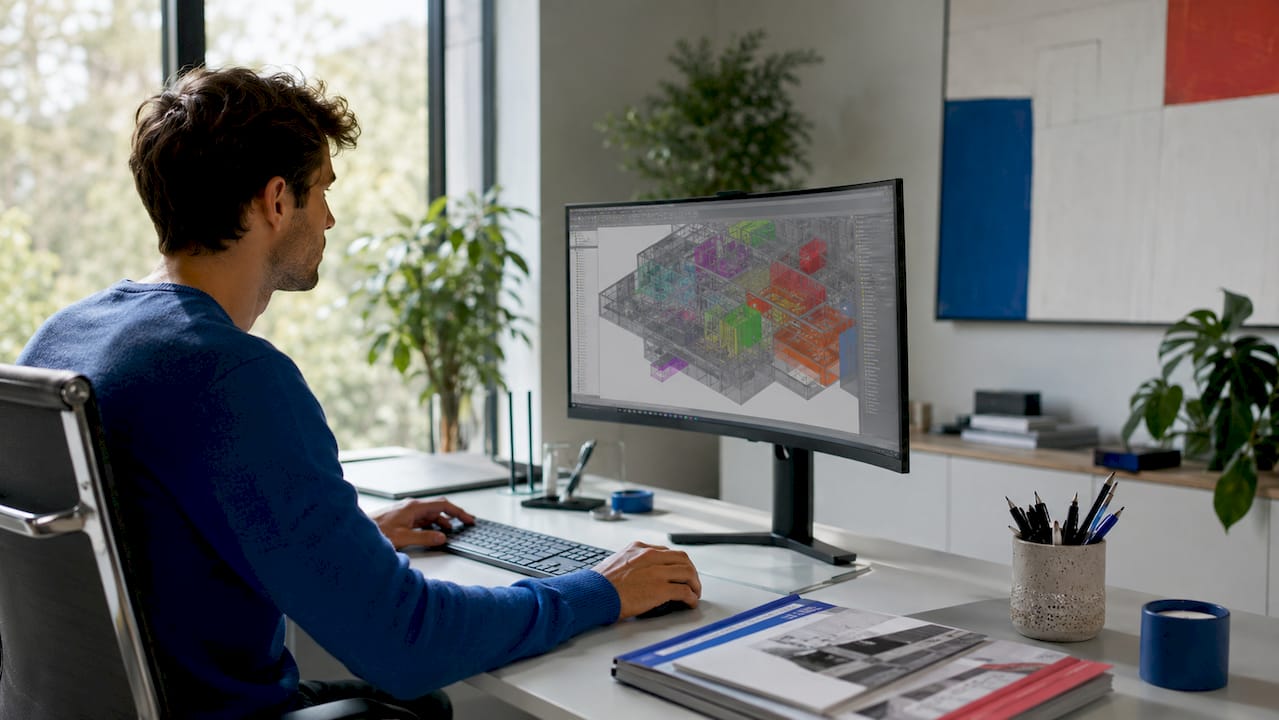
A Revit coordination model is a linked federated reference model that lets you review and align geometry from other disciplines without importing that geometry directly into your project. Think of it as a read-only overlay. You can see the structural steel, the MEP ductwork, or the civil survey data sitting in your Revit environment, but none of it becomes part of your host model. This is the core concept behind what is a Revit coordination model, and understanding it changes how you approach multi-discipline BIM collaboration. Supported file types include Navisworks NWD files and native DWG files from tools like Advance Steel.
What is a Revit coordination model and how does it work?
A coordination model enters your Revit project through Insert > Link > Coordination Model. That single menu path is where the workflow begins. Once linked, the file appears in your 3D views as a visual reference you can snap to, measure from, and compare against your own design geometry.
Revit 2024 introduced the ability to draw elements relative to coordination models using snapping features, which was a meaningful step forward for practical daily use. Before that update, coordination models were largely passive overlays. Now you can actually reference them while placing walls, columns, or structural elements.
The snap behavior has specific rules you need to know:
Snapping works at object endpoints only.
Midpoints and quadrant snaps are not supported on coordination model geometry.
The Measure tool works against coordination model objects.
Direct placement of dimension elements on coordination model objects is restricted.
Visibility and category controls for coordination models have improved in recent Revit versions, giving you more display flexibility.
The supported link types include Navisworks NWD and native DWG files, such as those exported from Advance Steel. This means a structural engineer can hand you a DWG of their steel framing, and you can link it as a coordination model without converting it or importing heavy geometry into your architectural model.
Pro Tip: Always test your snap behavior in a 3D view before committing to a coordination-based workflow on a live project. Snap availability depends on the view context, the active work plane, and how the coordination model was originally authored.
Why does the shared coordinate system matter so much?
Shared coordinates are the foundation of every successful Revit model coordination workflow. Without them, your linked models will not align, and no amount of snap precision will fix a model that is sitting 500 meters from where it should be.
Revit uses three reference points for every project: the Project Base Point, the Survey Point, and the Internal Origin. Each one serves a different purpose. The Internal Origin is the absolute center of the Revit coordinate space. The Project Base Point defines your building’s position relative to the site. The Survey Point ties your model to real-world geographic coordinates.
The recommended workflow for establishing shared coordinates across disciplines follows this sequence:
Designate a Building Coordination Model as the single source of truth for coordinate alignment across all discipline models.
Link a civil DWG file as the base reference and position it correctly relative to the Survey Point.
Import XML coordinate data from the civil file to align the Revit coordinate system with the site.
Acquire or publish shared coordinates from the Building Coordination Model to each discipline model (architectural, structural, MEP).
Verify alignment by overlaying all linked models in a federated 3D view before any design work begins.
The Building Coordination Model acts as the authoritative shared origin. Every discipline team acquires coordinates from it, not from each other. This prevents the compounding errors that happen when teams share coordinates in a chain rather than from a single source.
Common pitfalls that cause misalignment include:
Teams using Internal Origin instead of shared coordinates when linking models.
Coordinate origins agreed on verbally but never formally published through Revit’s coordinate tools.
Civil DWG files repositioned after coordinates were already acquired.
Establishing shared coordinates early in the project prevents coordination errors that are expensive and time-consuming to fix later. This step is not optional on any project with more than one discipline model.
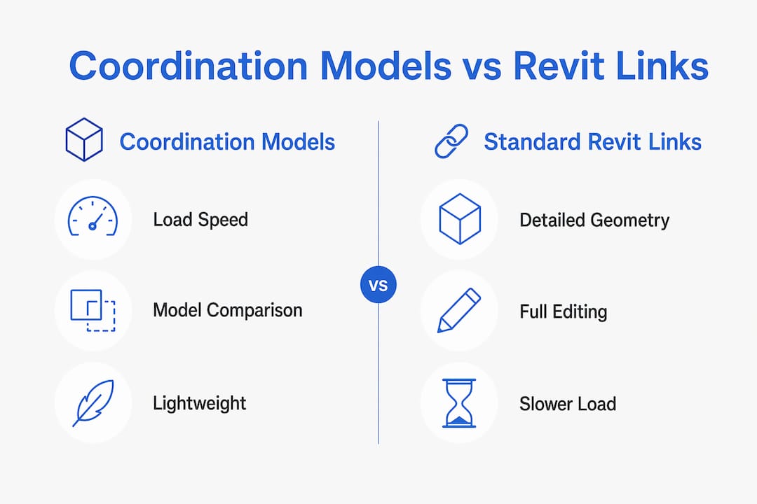
Coordination models vs. standard Revit links: which should you use?
The choice between a coordination model and a standard Revit link comes down to what you need to do with the referenced geometry. Both approaches have clear strengths and real limitations.
Feature | Coordination model | Standard Revit link |
Load speed | Faster, lightweight | Slower, full geometry |
File types supported | NWD, DWG (Advance Steel) | RVT only |
Snap support | Endpoints only | Full snap options |
Dimensioning | Restricted, measure-only | Full dimension placement |
Annotation | Not supported | Supported |
Geometry accuracy | Can show distortions | Accurate |
Visibility controls | Improving in recent versions | Full category control |
Best use case | Reference and clash review | Full design coordination |
Coordination models load faster than standard Revit links and support model comparisons, which makes them useful on large projects where performance matters. That speed advantage is real and significant when you are working with complex federated models.
The limitations are equally real. Current coordination models can display inaccurate geometry, including coordinate-related distortions, and they do not support annotations or full visualization controls. This means you cannot use a coordination model as a substitute for a properly linked RVT file when you need to dimension against structural elements for documentation.
The practical rule is straightforward. Use a coordination model when you need a lightweight reference for clash checking, visual context, or snap-based placement. Use a standard Revit link when you need full documentation accuracy, annotations, or complete category control.
Best practices for working with coordination models effectively
Getting the most from the Revit coordination process requires planning your workflow before you start placing elements. The biggest mistake professionals make is treating coordination models like standard Revit links and then being surprised when dimensioning fails.
Enable snap settings explicitly. Go to Manage > Snaps and confirm that snapping to coordination models is active. Do not assume it is on by default.
Test snap points in 3D views first. Snap availability depends on the view type, the active work plane, and how the coordination model was authored. A snap that works in one view may not work in another.
Plan for a measure-and-reference workflow. Use the Measure tool to capture distances from coordination model geometry, then place your dimension elements on host-model lines or reference planes. Dimensions placed on host geometry remain accurate and exportable.
Validate alignment before design work begins. Overlay all discipline models in a federated 3D view and check that shared coordinates are working correctly. Fix misalignment at this stage, not after walls are placed.
Use coordination models to support performance on large projects. Linking NWD files instead of full RVT files reduces model load times and keeps your working environment responsive.
Pro Tip: When collaborating across disciplines, use the S15studio Revit worksharing course to understand how shared coordinates interact with Revit’s worksharing tools. The two systems work together, and misunderstanding either one causes project-wide alignment problems.
The Revit modeling best practices for multi-discipline coordination all point to the same principle: agree on your coordinate system, test your links, and document your workflow decisions early. Teams that skip these steps spend far more time fixing errors than they saved by skipping them.
Key Takeaways
A Revit coordination model is a lightweight linked reference file that enables cross-discipline alignment without importing heavy geometry into your host model.
Point | Details |
Core definition | A coordination model is a linked federated reference, not an imported geometry set. |
Supported file types | Navisworks NWD and DWG files link as coordination models inside Revit. |
Snap limitations | Snapping works at endpoints only; midpoints and quadrants are not supported. |
Shared coordinates | Establish a Building Coordination Model as the single coordinate source early in every project. |
Dimensioning workflow | Measure from coordination geometry, then place dimensions on host-model lines or reference planes. |
My honest view on where coordination models stand right now
I have watched coordination model adoption grow steadily, and I think the technology is genuinely useful but still misunderstood by most teams. The common mistake I see is that professionals link a coordination model, discover the dimensioning restrictions, and then abandon the workflow entirely. That is the wrong response.
The right response is to adjust your documentation approach. Measure from the coordination geometry, reference it visually, and place your dimensions on host-model elements. Once you accept that limitation, the workflow becomes genuinely productive.
The performance argument for coordination models is strong on large projects. Linking a Navisworks NWD file instead of a full RVT keeps your model fast and your team focused. The geometry accuracy issues are real, but they matter less for clash review and visual reference than they do for precise documentation.
What I want to see from Autodesk is better geometry accuracy and full annotation support. The 2024 updates moved in the right direction with improved snap features. The workflow is not complete yet, but it is worth building into your practice now so you are ready when the remaining limitations are resolved. Teams that wait will be behind.
— Steve
Build your Revit coordination skills with S15studio
Coordination models are one piece of a larger BIM collaboration picture. Understanding how they connect to worksharing, shared coordinates, and multi-discipline workflows takes structured practice.
S15studio offers training from introductory Revit concepts through to advanced coordination and collaboration techniques. Steve Fagan, an Autodesk Certified Trainer, built these courses around real project workflows, not theory. Whether you are starting with Revit for beginners or ready to go deep on coordination and BIM collaboration, the complete Revit training program covers the skills you need to work confidently on multi-discipline projects.
FAQ
What is a Revit coordination model?
A Revit coordination model is a linked federated reference file, such as a Navisworks NWD or DWG, that provides visual and snap-based context inside Revit without importing geometry into the host model.
What file types work as coordination models in Revit?
Revit supports Navisworks NWD files and native DWG files, including those exported from Advance Steel, as coordination model link types.
Why can’t I dimension directly on a coordination model?
Snap controls on coordination models support endpoints only, and direct dimension placement on coordination model objects is restricted. The correct workflow is to measure from coordination geometry and place dimensions on host-model lines or reference planes.
How do I set up shared coordinates for coordination models?
Designate a Building Coordination Model as the single coordinate source, link a civil DWG as the base reference, and then acquire or publish shared coordinates from that model to each discipline file before design work begins.
When should I use a coordination model instead of a standard Revit link?
Use a coordination model when you need a lightweight reference for clash review, visual context, or snap-based placement. Use a standard Revit link when you need full annotation support, accurate geometry, and complete category control for documentation.
Recommended
Comments