
AutoCAD Architectural Drawing Setup: 2026 Guide


AutoCAD architectural drawing setup is the process of configuring workspace settings, drawing units, layer standards, and layout tabs before you place a single line on screen. Done correctly, this configuration produces submission-ready drawings that meet professional standards and keeps your team working from the same baseline. Done poorly, it creates scaling errors, inconsistent line weights, and hours of rework. This guide walks architects, architectural technicians, and students through every critical setting, from the UNITS command to locked viewport scales, so your drawings are accurate from day one.
How to configure AutoCAD architectural drawing setup correctly
The first decision you make in any new drawing is the unit system. Setting drawing units uses the UNITS command. Type UNITS at the command line, then select “Architectural” from the dropdown. This format displays measurements in feet and inches with fractional representation, which matches the way architects dimension floor plans and sections. Getting this wrong early means every dimension on your drawing is untrustworthy.
Workspace selection matters just as much as units. Autodesk recommends the “Drafting & Annotation” workspace for 2D architectural drafting because it organizes the ribbon and toolbars around the tools you actually use. Switch workspaces via the status bar at the bottom right of the screen or by typing WSSETTINGS at the command line.
Here is the recommended sequence for initial drawing configuration:
Type UNITS, select “Architectural,” and set precision to the nearest 1/16 inch.
Switch to the “Drafting & Annotation” workspace via the status bar.
Set the drawing limits to match your intended sheet size at full scale.
Confirm LTSCALE and DIMSCALE are set to 1 for model space work.
Save the file immediately as your base template (.dwt format).
Pro Tip: Save a configured .dwt template file with units already set to Architectural. Every new project starts from this template, and you eliminate the risk of a team member opening a metric default and drafting an entire floor plan in millimeters.
Choosing the right default template early is the single most effective way to prevent scaling errors and inconsistencies across a project team. A misconfigured template forces every team member to fix the same problem independently.
What are the layer naming standards for architectural drawings?
Layers are the organizational backbone of any AutoCAD architectural floor plan. Each layer groups a specific building element, controls its visual properties, and lets you isolate or hide content without deleting geometry. Without a consistent naming system, drawings become unreadable and impossible to hand off to consultants.

The industry standard uses a prefix system. “A” denotes architectural elements, so walls become A-WALL, doors become A-DOOR, and windows become A-GLAZ. This prefix convention, widely used in professional practice, makes it immediately clear which discipline owns each layer and what it contains.
Professional submission drawings require specific layer naming conventions and line weights set for legibility. The table below shows a practical starting point for an architectural layer set:
Layer name | Color | Line weight | Purpose |
A-WALL | Red (1) | 0.50 mm | Structural and partition walls |
A-DOOR | Yellow (2) | 0.35 mm | Door swings and frames |
A-GLAZ | Cyan (4) | 0.35 mm | Windows and glazed elements |
A-FURN | Green (3) | 0.25 mm | Furniture and fittings |
A-TEXT | White (7) | 0.18 mm | Annotation and labels |
A-DIMS | White (7) | 0.18 mm | Dimensions |
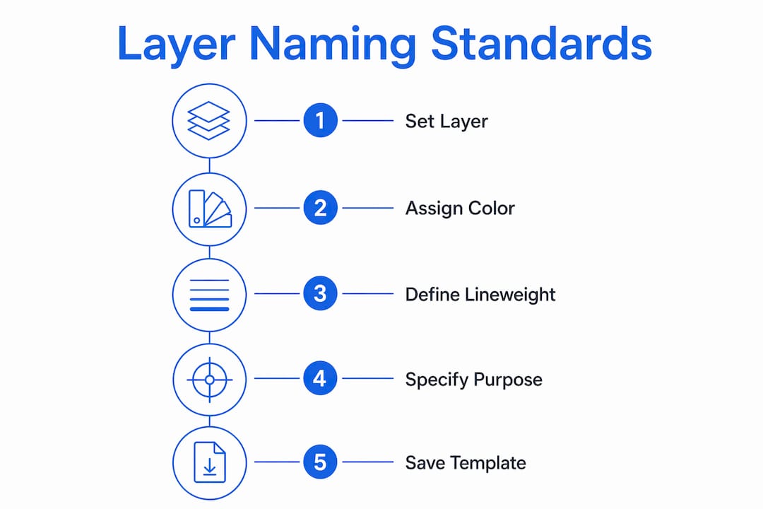
Color and line weight assignment for layers directly affects legibility and professional presentation in printed drawings. Walls print at 0.50 mm so they read as the dominant element. Text and dimensions print at 0.18 mm so they support the drawing without competing with it.
Layer controls give you real workflow power beyond just organization:
Freeze layers you are not actively editing to speed up display regeneration.
Lock layers to prevent accidental edits while keeping them visible.
Turn off layers to simplify the view without removing geometry.
Isolate a single layer using the LAYISO command when you need to focus on one building element.
Pro Tip: Once your layer set is complete, save the drawing as a .dwt template. Every future project inherits the full layer structure, color coding, and line weights without manual recreation. S15studio covers this exact workflow in its AutoCAD training courses.
For a deeper look at drawing standards in AutoCAD, including line type scales and text styles, the S15studio resource library has dedicated guides for design professionals.
What is the AutoCAD layout tab and how does it work?
The AutoCAD layout tab is where you prepare drawings for printing at a specific scale. Model Space is where you draw all geometry at a 1:1 real-world scale. Layout tabs, which represent Paper Space, are where you arrange that geometry on a sheet, assign a print scale, and place your title block. These two environments serve completely different purposes.
Model space should always be drawn at 1:1 real-world scale. All scaling happens in Layout tabs through viewports. A viewport is a window cut into Paper Space that looks into Model Space. You set the viewport scale to 1:50 or 1:100, and AutoCAD handles the math. This is the correct workflow, and it is the one that professional practices follow.
Many new users misunderstand layout tabs and waste time managing geometry in Paper Space instead of Model Space. The result is drawings that look correct on screen but plot at the wrong scale or cannot be edited without breaking the sheet layout.
Follow this sequence to set up a layout tab correctly:
Right-click a layout tab and rename it to match the sheet (e.g., “Floor Plan L01”).
Delete the default viewport AutoCAD creates automatically.
Set the page setup: right-click the tab, select “Page Setup Manager,” and assign the correct paper size and plotter.
Insert your title block as a block reference in Paper Space.
Create a new viewport using the VIEW > Viewports > 1 Viewport command.
Double-click inside the viewport to activate it, then type the scale into the viewport scale box on the status bar (e.g., 1:50).
Lock the viewport display by clicking the lock icon on the status bar. This prevents accidental panning inside the viewport.
Trying to scale geometry in Model Space causes mistakes that are difficult to reverse. Lock your viewports after setting the scale, and you eliminate the most common plotting error in architectural drafting.
Pro Tip: Create a separate layout tab for each drawing sheet in your set. Name them consistently (e.g., “A101 Floor Plan,” “A201 Elevation”) so the sheet index matches your tab order. This makes navigating large drawing sets fast and predictable.
How do you avoid common AutoCAD setup mistakes?
Setup errors compound over time. A wrong unit setting on day one produces incorrect dimensions on every drawing that follows. The most common mistakes in architectural drafting configuration are fixable, but only if you know what to look for.
The most frequent errors are:
Drawing in the wrong units. Metric drawings in an architectural project, or vice versa, produce dimensions that are off by a factor of 25.4. Always confirm units before drawing anything.
Placing geometry on Layer 0. Layer 0 is a default layer, not a working layer. All architectural elements belong on named layers like A-WALL or A-DOOR.
Scaling in Model Space. Scaling a floor plan down to fit a sheet in Model Space breaks the 1:1 relationship and makes future editing unpredictable.
Ignoring default save format. If your team uses AutoCAD 2020 and you save in the 2026 format, colleagues cannot open your files. Set the default save format under Options > Open and Save.
“Expert users maintain strict layer discipline and use templates with predefined layers, styles, and naming for speed and compliance. The template is not a convenience. It is the foundation of every drawing you produce.”
DesignCenter (ADCENTER) is the tool most architects overlook for maintaining standards. Access it with Ctrl+2 or by typing ADC. It lets you copy layers, blocks, text styles, and dimension styles from any existing drawing into your current file. This means your standard layer set travels with you even when you start from someone else’s template.
For a full breakdown of common drafting errors and how to fix them, the S15studio blog covers the most damaging mistakes architects and students make during setup and early drafting.
Pro Tip: Use Layer States to save and restore specific layer configurations. Save a “Design” state with all layers on, a “Presentation” state with furniture and dimensions off, and a “Structural” state showing only walls and columns. Switch between them in seconds.
Key Takeaways
A correct AutoCAD architectural drawing setup, built on proper units, named layers, and locked viewport scales, is the foundation every professional drawing depends on.
Point | Details |
Set units before drawing | Use the UNITS command to select Architectural format before placing any geometry. |
Use the right workspace | Switch to “Drafting & Annotation” via the status bar for optimized 2D drafting tools. |
Name layers with prefixes | Use A-WALL, A-DOOR, and A-GLAZ conventions with correct line weights for submission drawings. |
Draw at 1:1 in Model Space | All scaling belongs in Layout tab viewports, not in Model Space geometry. |
Save a .dwt template | Store your layer set, units, and styles in a template file to maintain consistency across projects. |
Why setup is the most underrated skill in architectural drafting
Most training courses rush past setup to get to the “interesting” parts: drawing walls, placing doors, building up a floor plan. I understand the impulse. Setup feels administrative. It does not look like progress. But in fifteen years of working with architects and technicians, the drawings that cause the most problems in practice are almost never the ones with bad design. They are the ones with bad setup.
I have seen entire project sets rebuilt from scratch because the original drafter worked in millimeters on an architectural project. I have seen consultants reject drawing packages because the layer naming was inconsistent and their BIM coordination software could not parse the files. These are not skill failures. They are setup failures, and they are completely avoidable.
The architects who work fastest are not the ones who draw fastest. They are the ones who spend twenty minutes at the start of a project configuring a template that saves them two hours on every drawing that follows. Layer discipline, locked viewports, and a solid .dwt file are not advanced techniques. They are the baseline habits that separate professional output from student work.
If you are an architecture student, learn this before you learn anything else. If you are a technician who has been skipping setup, fix your template this week. The quality of your drawings depends on it more than any command you will ever learn.
— Steve
Build your AutoCAD skills with S15studio
S15studio offers structured AutoCAD training built specifically for architects, architectural technicians, and students who want to move beyond trial and error.

The Mastering AutoCAD course at S15studio covers every element of professional drawing configuration, from unit setup and layer standards to layout tabs and plotting workflows. Courses are project-based, taught by Autodesk Certified Trainer Steve Fagan, and designed to build the real-world skills that practices actually hire for. Whether you are starting from scratch or filling gaps in your current workflow, S15studio has a course path that fits where you are right now.
FAQ
What is AutoCAD architectural drawing setup?
AutoCAD architectural drawing setup is the process of configuring units, workspace, layers, and layout tabs before drafting begins. Correct setup produces accurate, submission-ready drawings and prevents scaling and layer errors.
What is the AutoCAD layout tab used for?
The AutoCAD layout tab represents Paper Space, where you prepare drawings for printing at a specific scale. Model Space holds geometry at 1:1 scale, and layout viewports apply the print scale.
What layer naming convention should architects use in AutoCAD?
Architects use a prefix system where “A” denotes architectural elements. Examples include A-WALL for walls, A-DOOR for doors, and A-GLAZ for windows, with line weights set to 0.50 mm, 0.35 mm, and 0.35 mm respectively.
What is an AutoCAD drawing template file?
An AutoCAD drawing template (.dwt) is a preconfigured file that stores units, layer names, line weights, text styles, and dimension styles. Starting every project from a template keeps drawings consistent across a team.
Why should you draw at 1:1 scale in Model Space?
Drawing at 1:1 scale in Model Space keeps all geometry at real-world dimensions, which makes editing accurate and predictable. Scale is applied only in layout viewports when preparing sheets for printing.
Recommended
Comments